
0 30v Variable Power Supply Circuit Diagram Using Lm317
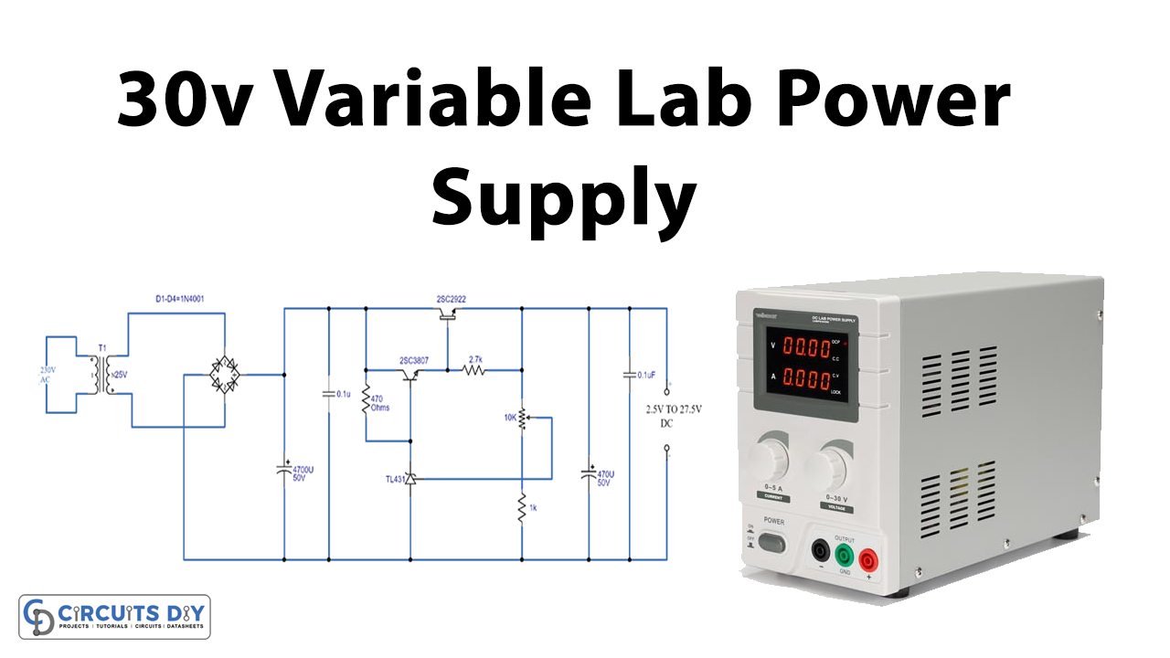
0-30V Stabilized Variable Power Supply with Current Control. This is high quality 0-30v stabilized variable power supply circuit diagram. You will able to adjust the output voltage from 0 volt up to 30 volt DC. You also able to adjust the current output value from 0.002 A to 3 A. This variable power supply incorporates an electronic output.
dc power supply circuit diagram Wiring Diagram and Schematics
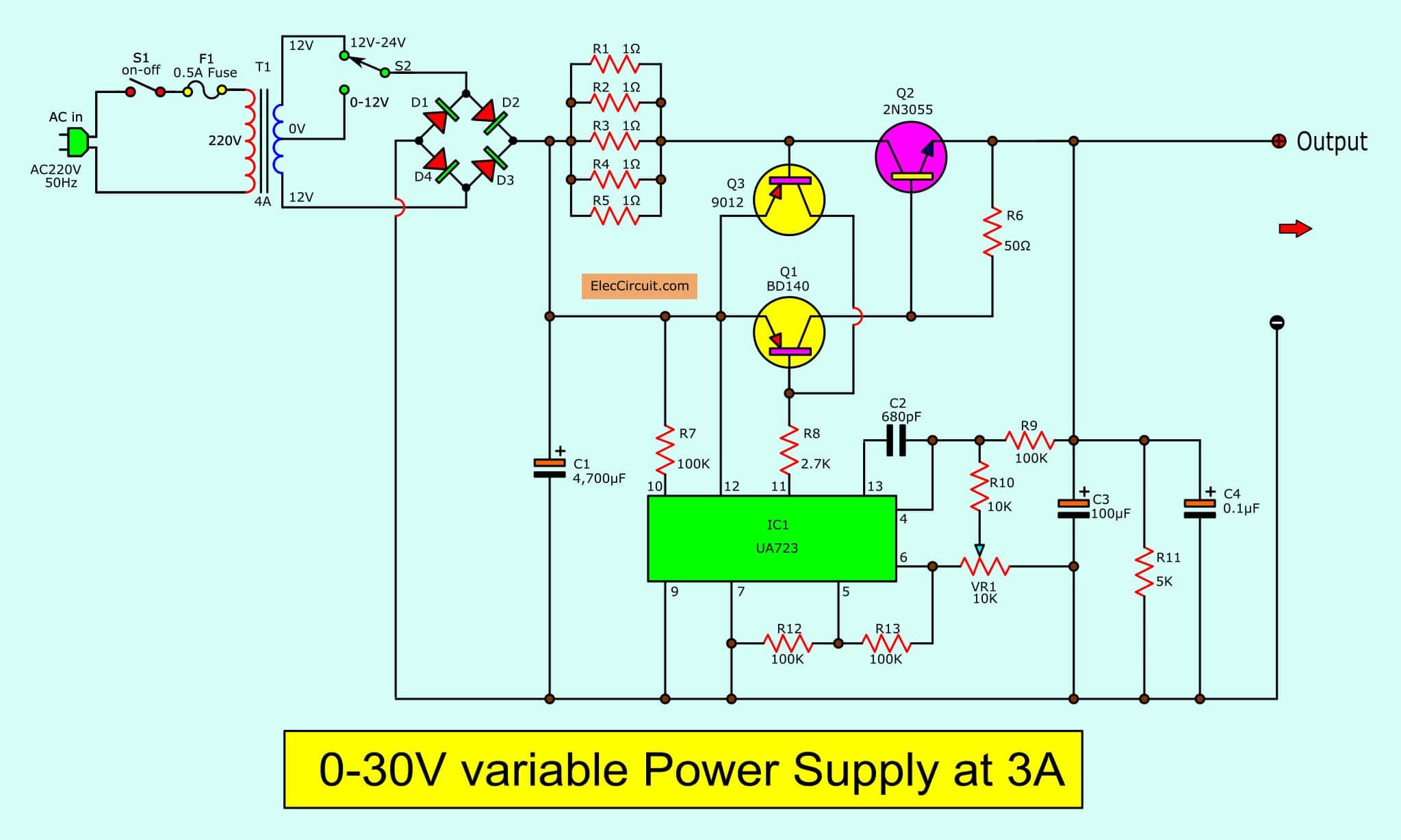
0-30V Variable Power Supply circuit Diagram at 3A - ElecCircuit.com :: Home » Power supply » Variable Supply » 0-30V Variable Power Supply at 3A 0-30V Variable Power Supply at 3A Last Updated on: October 21, 2022 by Apichet Garaipoom This is a 0-30V Variable Power Supply circuit.
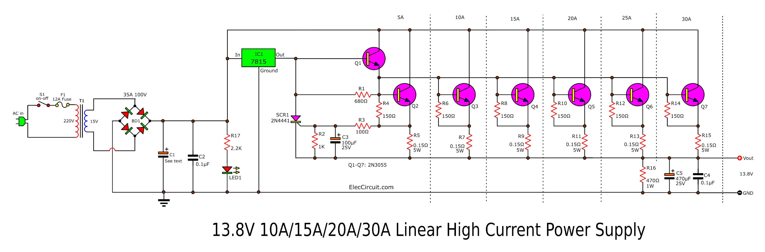
High Current 12V13.8V at 30A,25A,20A,15A Power Supply Elec Circuit
Question 2 A technician builds a simple half-wave rectifier circuit for a project, but is surprised to find that the diode keeps failing: This comes as a surprise because the diode has a repetitive peak reverse voltage rating of 50 volts, which the technician knows is greater than the peak voltage output by the step-down transformer.
030V Variable Power Supply circuit Diagram at 3A
How the 0-30VDC variable power supply circuit works: The diode D8 is a 5.6 V zener, which here operates at its zero temperature coefficient current. The voltage in the output of U1 gradually increases till the diode D8 is turned on. When this happens the circuit stabilises and the Zener reference voltage (5.6 V) appears across the resistor R5.
Dc Simple Circuit Diagram
This Power Supply Has Following Features: Input Voltage 12V DC. Input Current 3A. Output Voltage (1-30V) Continuously Adjustable. Output Current (300mA-6A) Continuously Adjustable. Output ripple 50mV. Constant Voltage And Constant Current. Aditional 5V Constant Output. Short Circuit Projection. Here's The Complete Tutorial And Demonstration Video.
Dc Regulated Power Supply Circuit Diagram
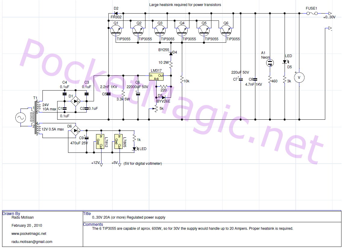
0-28V, 6-8A Power Supply Circuit Diagram using LM317 and 2N3055 This design can produce a current of 20 amps with little modification (use proper rating transformer and a huge heat sink with fan). Huge heat sink is required in this circuit, as 2N3055 transistors produce large amount of heat at full load. Circuit Components
030V Stabilized Variable Power Supply With Current Control Circuit Diagram Lm324 Variable
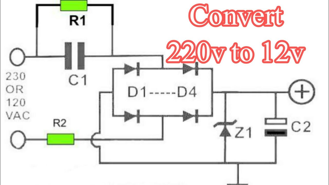
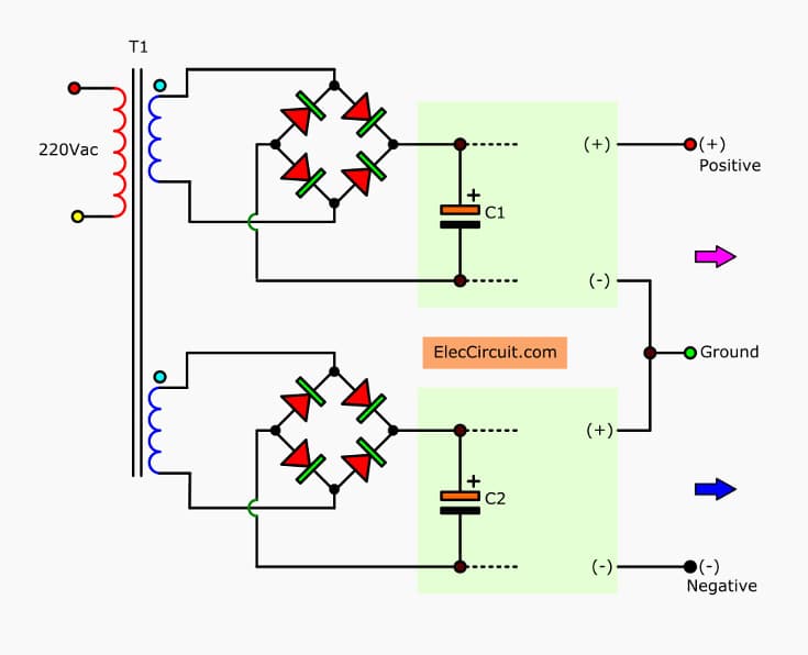
The diagram shows how the diodes are connected to the transformer. Though, the two diodes work in tandem and tackle both the halves of the AC signal and produce a full wave rectification, the employed method is not efficient, because at any instant only one half winding of the transformer is utilized.
Modifying power supply circuit for either higher current &/or voltages and maybe implement
The power supplies are the mainstay of electronic circuits. The power supply circuits can be designed in many ways. There can be adjustable power supplies or can be fixed voltage power supplies. A power supply circuit is rated by the voltage or range of voltage it supplies and the maximum current it allows to draw by a load. Secondly, the households are provided with AC voltages as main.
12v 30 Amp Power Supply Circuit Diagram
A power supply for all general circuits, Based on a stablized DC voltage of 30 volt This power supply is meant as an auxiliary or as a permanent power supply for all common circuits based on a stabilized DC voltage between 3 and 30V provided that the consumption does not exceed 3A. Of course this power supply unit can also be used for other.

030V Variable Power Supply circuit Diagram at 3A
This is high quality 0-30v stabilized variable power supply circuit diagram. You will able to adjust the output voltage from 0 volt up to 30 volt DC. You also able to adjust the current output value from 0.002 A to 3 A.

Ac To Dc Regulated Power Supply Circuit Diagram Wiring Diagram
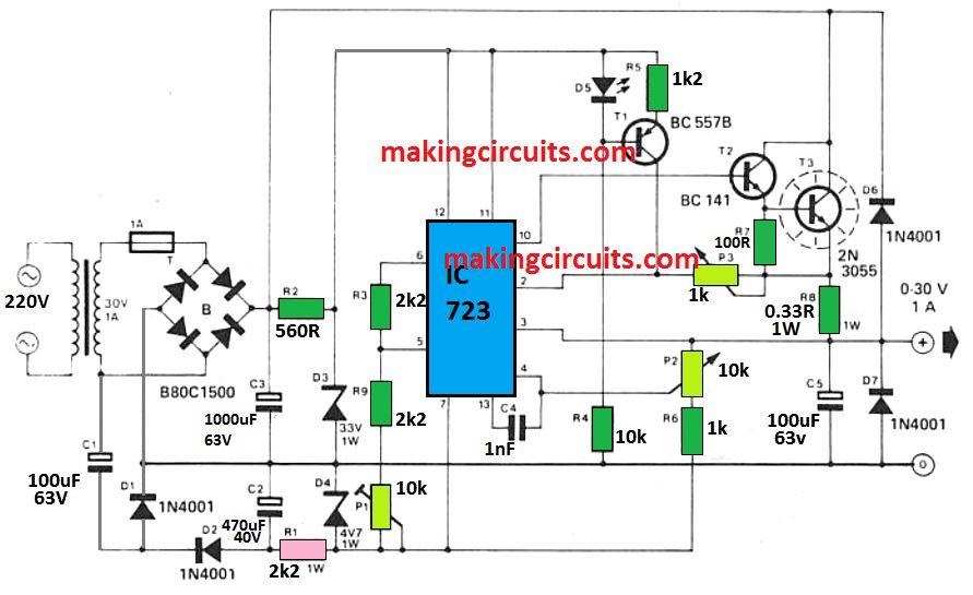
This is a 0-30V 5A variable benchtop power supply circuit, with a voltage and current adjustable system. The output voltage 0-30V and a maximum current of 5A. Use LM723 as a voltage regulator designed primarily for series regulator applications. By itself, it will supply output currents up to 150 mA.

0 30V Variable Power Supply Circuit Diagram Using Lm317
This is a high quality power supply with a continuously variable stabilised output adjustable at any value between 0 and 30VDC. The circuit also incorporates an electronic output current limiter that effectively controls the output current from a few milliamperes (2 mA) to the maximum output of three amperes that the circuit can deliver.

This project is based on the 030 VDC Stabilized Power Supply with Current Control 0.0023 A and
Step 1: Mount and Solder the Components As Presented in the Schematic Diagram To start designing this circuit, you will need a heat sink to attach LM317, BD139 and TP3055 transistors. Then, mount these components on a PCB board and cut the extra legs of the components soldered with a cutting plier.
0 30 V Regulated Power Supply Circuit
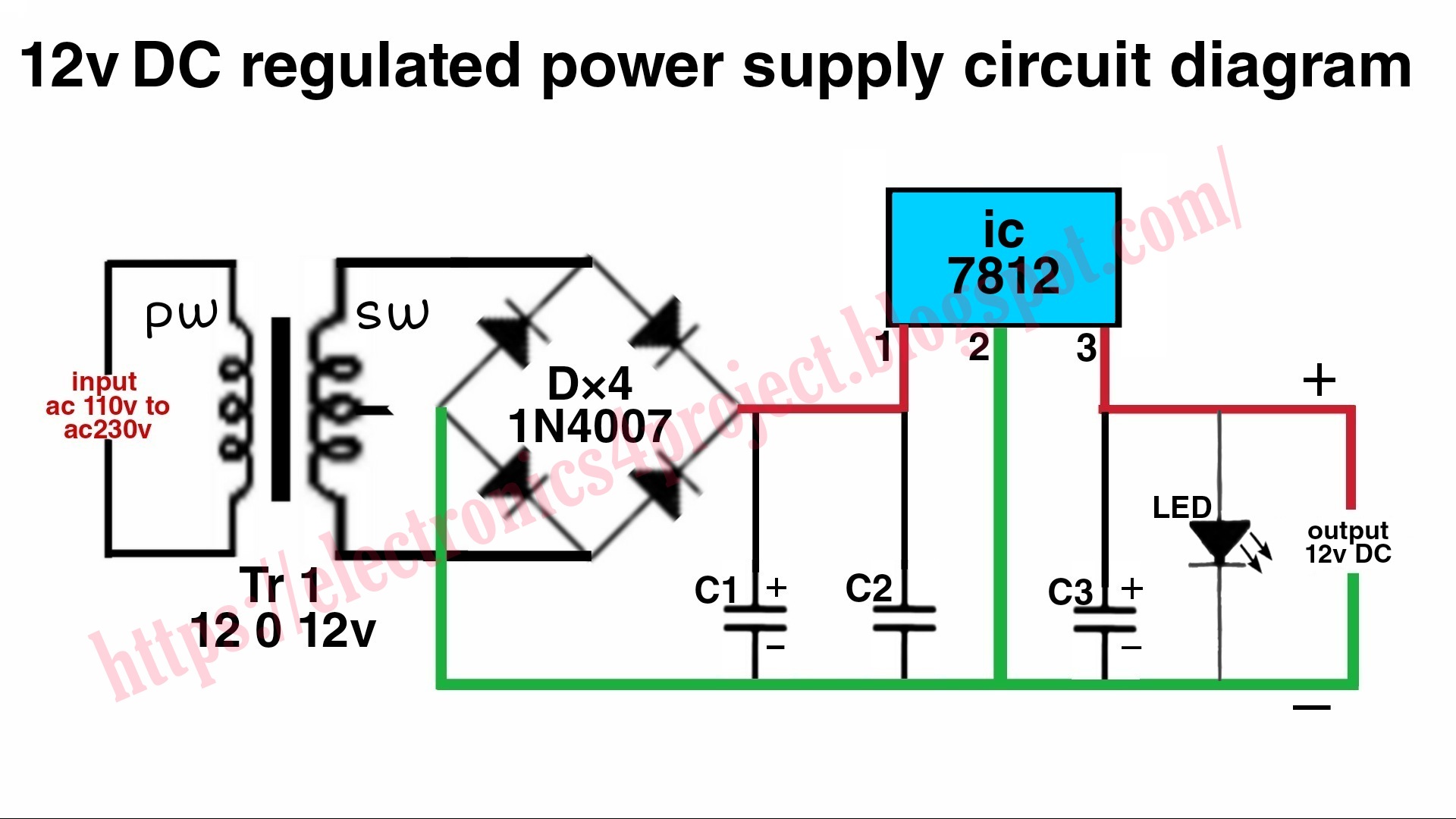
The working of the circuit is as follows. A transformer is used to step down the AC supply to 24V at 2A. A bridge rectifier is used to convert this voltage to DC. This pulsating DC is filtered using the capacitor to get a clean DC and is given to LM317 which is a variable voltage regulator IC.

Dc Power Supply Circuit Diagram
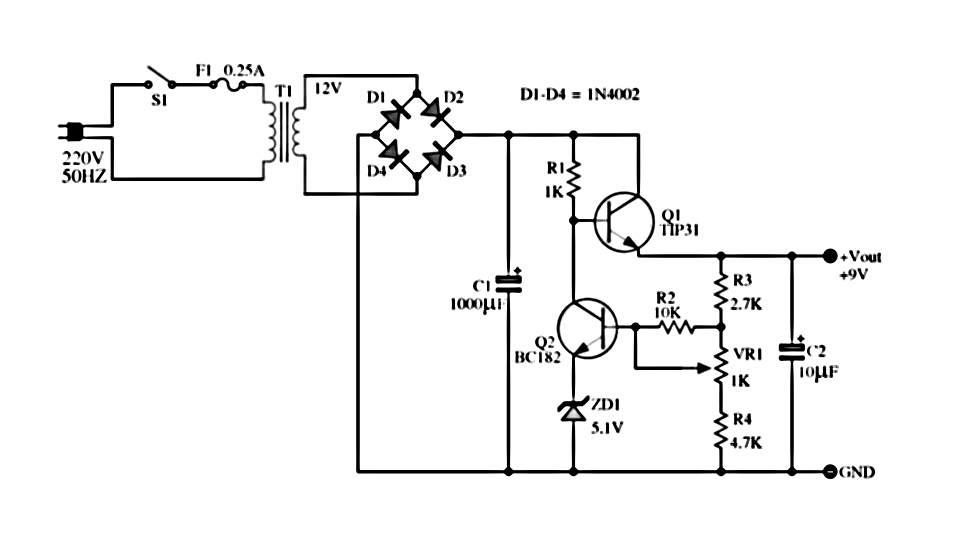
9 Volt 2 Ampere DC Power Supply Circuit Diagram.. The regulation of voltage, of expense becomes with potentiometer R1 from 0v-30v DC roughly. In order to we achieve 30 V, will should the transformer of supply TR1, it gives all the current that it asks the load, differently the output voltage it will be found in the levels of 26 V roughly..
0 30v Power Supply Circuit Diagram Wiring Diagram PDF
This is the circuit diagram of the voltage and current regulator circuit that can give the output of min 1.5v to max of 30v DC and current min 0 to max 10A. Use the 5k potentiometer for the adjustment of voltage and the 10k potentiometer with BD139 transistor for adjustment of current.
